In this series we now have:
- set up our development environment for OpenGL and created our basic game loop class
- written a simple shader for drawing a colored quad
- Complied and Linked the Shader with the program.
Next we will create a quad by defining its vertices in the screen space and proceed to draw it. To define the vertices in screen space we need to understand how the screen co-ordinates work with openGL. Here is a diagram showing that:
The X axis runs horizontally from -1 (left of the screen) to 1 (right) and the Y Axis runs vertically from -1 (bottom) to 1 (top) as shown in the image.
A quad has four vertices which can be drawn as a set of two triangles. Each of the four vertices has X and Y position. First we create an array that will hold the quad vertice data using Vectors.
Create Quad vertices Array
Include the vector header file and use the std namespace. In the GameMain.mm class add the following lines before the constructor.
#include <vector>

using namespace std;
Now we are ready to declare and fill out our quad vertex array. Although we might think that we require only the X and Y positions of the vertices we are required to provide the Z and W component of the vertex as well. This is because the quad is a plane in 3D space. The Z component of the vertex position could be used to order the quad in depth when we have multiple planes later on. This order is important for which plane is drawn in top and which is drawn on the bottom when there is an overlap. The W component is added to the 3D vertex data to make it homogeneous. Explanation on homogeneous co-ordinate and why they are used can be found here.
We will define a quad that is one fourth the size of the screen and is at the center of the screen. In the Initialize() function of GameMain class we add the following lines at the top of the function.
/************************/

vector<float> geometryData;

//4 floats define one vertex (x, y, z and w), first one is lower left

geometryData.push_back(-0.5f); geometryData.push_back(-0.5f); geometryData.push_back(0.0); geometryData.push_back(1.0);

//we go counter clockwise, so lower right vertex next

geometryData.push_back(0.5f); geometryData.push_back(-0.5f); geometryData.push_back(0.0); geometryData.push_back(1.0);

//top left vertex is last

geometryData.push_back(-0.5f); geometryData.push_back(0.5f); geometryData.push_back(0.0); geometryData.push_back(1.0);

//top right vertex is last

geometryData.push_back(0.5f); geometryData.push_back(0.5f); geometryData.push_back(0.0); geometryData.push_back(1.0);
Create and Bind The Geometry Buffer
Now that we have the position data we set up the geometry buffer which will hold the data and send it to the GPU for drawing. First we create the variable that will hold the buffer’s ID in GameMain.h inside the GameMain class’s private variable declaration area.
//our vertex buffer containing the geometry data for our quad

unsigned int m_geometryBuffer;

//locations for the vertex and color attribute in the shader

int m_positionLocation;
In GameMain class’s Initialize() before we create the shader object and after we have filled in our vertex data we add the following lines to create and bind the geometry buffers. They are OpenGL function calls that you can read about in from the OpenGL’s documentation.
//generate an ID for our geometry buffer in the video memory and make it the active one

glGenBuffers(1, &m_geometryBuffer);

glBindBuffer(GL_ARRAY_BUFFER, m_geometryBuffer);

//send the data to the video memory

glBufferData(GL_ARRAY_BUFFER, geometryData.size() * sizeof(float), &geometryData[0], GL_STATIC_DRAW);
Next we query the shader for the position attribute’s location where we need to attach out buffer. At the end of the Initialize() add the line
//get the attachment points for the attributes position and color

m_positionLocation = glGetAttribLocation(m_shader->getProgram(), "position");
That is it! We have successfully created the vertex buffer to hold our Quad’s vertex data. In the next section we will draw our quad on the screen.
Drawing the Quad
Below is the code for drawing to be put into the Draw() function of the GameMain class.
glEnableVertexAttribArray(m_positionLocation);

//bind the geometry VBO

glBindBuffer(GL_ARRAY_BUFFER, m_geometryBuffer);

//point the position attribute to this buffer, being tuples of 4 floats for each vertex

glVertexAttribPointer(m_positionLocation, 4, GL_FLOAT, GL_FALSE, 0, NULL);

//initiate the drawing process

glDrawArrays(GL_TRIANGLE_STRIP, 0, 4);

glDisableVertexAttribArray(m_positionLocation);
The first thing we do is enable the Vertex Attribute in the shader (which is already set in the Initialize() function). We then bind the vertex buffer by specifying that it is an array of data and then specifiy the type of data that will go into the GPU using the glVertexAttribPointer function call. Here the arguments define the type and size of data that will be bound to the buffer. We then proceed to draw the Triangles and disable the vertex array once we are done.
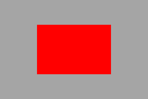
Running the code now you should see a red colored Quad on the screen. Here is a screen shot of the simulator.
You can grab the project files from the GIT repository tagged vOGL_2D.004.
In the next post we will texture our Quad using an image.

